PREREQUISITE STUDY:
It is recommended that students, before attempting to read the material on this web page, first study the web page titled: FNR CONCEPT so that they have an elementary understanding of what a Fast Neutron Reactor (FNR) is and how it works.
FNR DEFINITION:
The term Fast Neutron Reactor (FNR) is generically quite broad. However, for the purpose of this web site a FNR is a fast neutron reactor with sodium bonded metallic fuel rods, sealed metal fuel tubes, liquid sodium primary coolant, NaK secondary coolant, a fertile fuel blanket and a surrounding liquid sodium guard band.
FNR NUCLEAR POWER PLANT:
A Fast Neutron Reactor (FNR) nuclear power plant rated at 1000 MWt (300 MWe) has four major components.
a) There is an enclosed low pressure pool of liquid sodium.
b) Pure sodium is used because of its superior neutron properties and because NaOH melts at a lower temperature than KOH.
c) The reactor pool contains nuclear fuel bundles with a geometry that keeps the liquid sodium pool surface temperature at 460 degrees C.
d) In addition to producing heat these fuel bundles also breed fertile U-238 into fissile Pu-239;
e) There are up to 48 independent heat transport circuits that extract heat at an adjustable rate from the primary sodium pool.
f) Each heat transport circuit is connected to a dedicated remote steam generator;
g) Up to six steam generators are connected in parallel to drive a single synchronous steam turbogenerator rated at up to 37.5 MWe.
h) The FNR can support up to eight such turbogenerators for a gross electric power output capacity of up to 300 MWe.
i) There are cooling towers and district heating loops that absorb the low temperature heat emitted by the thermal electricity generation.
SUPPORT SYSTEMS:
a) There is a control system which varies the electric power output from each turbogenerator by controlling the corresponding heat extraction rate from the primary sodium pool;
b) There are redundant nuclear safety systems which monitor the reactor and the heat transport system and which safely shut down the reactor and/or heat transport circuits if any condition is abnormal.
c) There is provision for system maintenance and immediate suppression of any NaK fire by gravity draining NaK and nitrate salt from affected heat transfer loops into sealed below grade dump tanks.
d) There is enough cooling water stored on-site to safely remove fission product decay heat by evaporation in the absence of both external electric power and city water supply.
e) There is sufficient standby power available on-site to ensure safe removal of fission product decay heat in the absence of both AC grid line power and local power from steam generation.
f) There are redundant cryogenic systems for extracting argon from air.
FAST NEUTRON REACTOR GENERAL DESCRIPTION:
A practical fast neutron reactor is an assembly of metallic nuclear fuel rods inside sealed metal fuel tubes. Inside the metal fuel tubes, along with the metallic fuel rods, is sufficient liquid sodium to provide good thermal bond between the core fuel rods and the inside wall of the metal fuel tubes. In the fuel tubes, above the metallic fuel, is plenum space for collection and storage of inert gas fission products.
The use of liquid sodium trapped inside the sealed fuel tubes limits the absolute maximum safe fuel surface temperature to about 890 degrees C due to the contained sodium vapor pressure.
There is another concern that Pu melts at 639 degrees C and can potentially form an even lower 602 degrees C melting point eutectic with the iron in the fuel tube. To raise the melting point of this eutectic the fuel alloy contains 10% Zr by weight.
The metal fuel tubes reliably contain the fuel and fission products and thermally conduct heat from the fuel to the circulating primary liquid sodium. The metal fuel tubes are in bundles which maintain a stable fuel geometry. The maximum thermal power output and fuel cycle time of a FNR are limited by the properties of the fuel tubes.
The nuclear properties and the physical geometry of the fuel assembly are chosen to limit the core fuel rod peak centerline temperature to 560 degrees C. When cooler primary liquid sodium circulates past the outside of the fuel tubes the primary liquid sodium coolant acquires heat which can be used to generate electricity. The rate at which heat is extracted from the FNR is proportional to the temperature difference between the core fuel rod and the circulating primary liquid sodium.
There is a 50 degree C provision for fuel and cooling sodium flow non-uniformity. With perfect fuel and cooling sodium flow uniformity the maximum primary sodium temperature could be 510 degrees C. However, to compensate for fuel non-uniformity and sodium flow non-uniformity the maximum primary sodium surface temperature is chosen to be 460 degrees C.
The Fast Neutron Reactor (FNR) referred to herein uses a cylindrical pool of primary liquid sodium 20.0 m in diameter X 15.0 m deep. Immersed in middle of this primary sodium pool is an assembly of 464,192 vertical 9.525 mm OD X 6 m tall metal fuel tubes that maintain the liquid sodium pool surface temperature at 460 degrees C and that breed new fissile fuel atoms from fertile fuel feedstock. The central 299,776 fuel tubes contain the reactor core fuel. Each such core fuel tube can continuously safely emit 3.33 kWt of heat.
Around the primary sodium pool perimeter are 48 immersed intermediate heat exchange bundles which input hot primary liquid sodium from near the surface of the primary sodium pool and discharge cooler primary sodium about 5.3 m deeper in the primary sodium pool.
When there is no heat being extracted the liquid sodium pool surface temperature is about 460 degrees C. Under design full load conditions the liquid sodium pool temperature near the top center of the primary sodium pool is about 460 degrees C and the temperature in the lower part of the primary sodium pool is about 400 degrees C.
The FNR is assembled from truck portable modules. The fuel bundles, intermediate heat exchange bundles, pumps, sodium-salt heat exchangers, steam generators, turbogenerators, condensers, etc. used to assemble a FNR power plant are all modular and are individually road truck portable. The FNR heat transport systems and turbogenerators are supplied and assembled like a kit.
The primary sodium tank is assembled on site from pre-rolled (3 / 4) inch thick 304L stainless steel plate using deep pentration inert gas welding. The nested tanks are spaced using supplied fire brick.
FNR DESIGN CONCEPTS:
FNR design concepts are significantly different from water cooled reactor design concepts. FNR design concepts are reviewed below:
1) There is a single triple wall primary liquid sodium pool operating at atmospheric pressure. The primary sodium pool enclosure is designed to safely withstand a severe earthquake that produces horizontal accelerations of up to 1.25 g._____
2) For safety there are no penetrations through the primary sodium pool bottom or vertical side walls;
3) The primary sodium naturally density stratifies so that the hotest and least dense sodium floats on the top surface of the primary sodium pool;
4) Natural circulation causes the primary sodium to flow up through the hot fuel bundle cooling channels and down between the cooler intermediate heat exchange bundle tubes;
5) The walls and floor of the primary sodium pool and the intermediate heat exchange bundles are protected from neutron excitation and damage by a 1.7 m wide primary sodium guard band and by a gadolinium curtain. The sodium guard band, in addition to slowing and absorbing neutrons, provides thermal mass that limits the maximum rate of change of the primary sodium pool temperature.
6) The reactor fuel assembly consists of a chequer board pattern of alternating fixed and movable fuel bundles. The movable fuel bundles are inserted into the matrix of fixed fuel bundles from the bottom by liquid sodium operated hydraulic actuators. These actuators adjust the FNR core zone width and hence the FNR reactivity and hence the core zone temperature setpoint;
7) The insertion depth of the movable fuel bundles into the fixed fuel bundle matrix should be periodically adjusted over the fuel bundle operating life to keep the reactor sodium discharge temperature uniform across the FNR;
8) As long as its fuel concentration and fuel geometry are physically stable and the thermal load exceeds the fission product decay heat emission a properly designed FNR passively maintains its fuel temperature setpoint. This FNR uses metallic plutonium as its fission fuel element because of the large negative reactivity coefficient safety margin provided by the large temperature coefficient of expansion of plutonium.
9) For safety the FNR heat transport system is designed so that natural circulation of both the sodium and secondary NaK is sufficient to safely remove fission product decay heat, even if the top 4 m of liquid sodium is lost due to failure of up to two of the three nested cup steel pool walls;
10) To enable primary sodium pool structural maintenance there must be storage containers available into which the primary sodium can be transferred;
11) A FNR power reduction to a warm shutdown is achieved by reducing the NaK flow rate which slows heat extraction from the sodium pool by the intermediate heat exchangers. With no thermal load the sodium temperature will gradually settle at its setpoint of about 460 degrees C at which temperature the reactor reactivity is zero causing the nuclear chain reaction to stop.
If the average fuel temperature increases above the reactor setpoint the reactor reactivity becomes less than zero so no nuclear fission heat is produced. If the average fuel temperature decreases below the reactor setpoint sufficient nuclear heat is produced to raise the average fuel temperature back to its setpoint.
12) Cool shutdown of a FNR is achieved by partial withdrawal of movable fuel bundles from the matrix of fixed fuel bundles with the object of lowering the liquid sodium pool temperature to about 120 degrees C. Heat is slowly removed from the primary liquid sodium by use of NaK.
13) Cold shutdown of a FNR is achieved by fully withdrawing the movable fuel bundles, allowing the system to cool. During heat removal water in the steam generators will boil. The latent heat of evaporation associated with the released steam will remove heat allowing the liquid sodium to be cooled to about 120 degrees C.
14) Heat transport system maintenance and NaK fire suppression are enabled by release of the trapped argon gas that causes selected secondary sodium loops to drain into dump tanks.
15) The NaK circuits normally operates at about 0.5 MPa. In the event of a steam generator tube failure water flows into the molten salt loop. This water instantaneously boils producing water vapor which is vented to the atmosphere. The increase in salt loop pressure:
a) vents the water vapor to the atmosphere;
b) stops the injection water pump that feeds water to the steam generator;
c) opens drain valves that drain water from the shell bottom of the steam generator;
16) A fall in NaK level, such as might result from a NaK loop leak to the molten salt or to the sodium, is sensed and causes the molten salt to drain to its dump tanks. Then most of the remaining NaK in the heat transport loop immediately drains into its dump tank.
FUEL TUBE AND FUEL BUNDLE DETAIL:
The FNR fuel tube assembly consists of 945 active fuel tube bundles surrounded by 516 passive and up to 228 cooling fuel tube bundles. The fuel tubes, excluding end plugs, are 6.0 m long. Each fixed fuel tube bundle has 1.5 m long lower legs and a 0.40 m top extension which together with a 0.1 m core zone swelling allowance give it a total height of 8.0 m.
Each fuel bundle is composed of vertical 0.375 inch OD steel tubes X .036 inch wall, 6.0 m high that form a square lattice spaced (9 /16) inch center to center. The fuel tubes are sealed closed at both ends and contain the reactor core and blanket rods as well as internal liquid sodium to enhance thermal contact between the fuel rods and the tube walls and to chemically absorb corrosive fission product gases such as F, Cl, Br and I. Each fuel tube contains 1.7 m of plenum space sufficient for storage of inert fisson product gases.
Heat is removed from the fuel tube assembly by primary liquid sodium which flows upwards via natural convection through the fuel tube support grating and then up through the gaps between the fuel tubes. The fuel bundles can be fitted with bottom filters to trap any particles with dimensions over (1 / 32) inch. There is space immediately above the filters to allow liquid sodium cross flow so as to ensure liquid sodium can flow past all the active fuel tubes even if a particular filter section is obstructed.
Each movable fuel tube bundle contains 248 X 0.375 inch OD tubes. Each fixed fuel tube bundle contains 384 X 0.375 inch OD tubes.
The spacing between adjacent fuel tubes is maintained by spiral windings around every fuel tube and by diagonal plates within the fuel bundles. The fuel bundle bottom grating supports the fuel tubes while permiting vertical liquid sodium coolant flow. Some fuel tubes are missing from the regular lattice to allow space for the fuel tube bundle shrouds and fuel tube bundle diagonal steel plates which further stabilize the fuel tube positions.
Each active fuel tube contains a 1.8 m long blanket fuel rod stack, 1 X 0.6 m long core fuel rod and then another 1.8 m long blanket fuel rod stack. Each passive fuel tube contains a 4.2 m long blanket fuel rod stack.
During prolonged reactor operation the core fuel rods swell in length by about 15%. Each fuel tube contains a measured amount of liquid sodium. The top 1.7 m of each active fuel tube are nominally empty to provide sufficient plenum volume to relieve pressure stress resulting from formation of inert gas fission products and to store sufficient spare sodium to compensate for fuel tube material swelling. The plenum portion of the fuel tube bundle also serves as a chimney to enhance the natural circulation of the liquid sodium.
Each fixed fuel tube bundle is supported and stabilized by its 1.5 m high legs that plug into sockets on the top of the 1.5 m high steel lattice which rests on ball bearings supported by the bottom of the primary sodium pool. At its top each fixed fuel bundle is bolted to its four nearest neighbours to provide the fixed fuel bundle matrix lateral stability. Additional lateral stability can potentially be realized using a formed steel belt around the outside of the assembly of fuel bundles.
FNR OUTPUT CAPACITY CONSTRAINTS:
The FNR core zone normally operates at the edge of fission criticality. The requirement for fission criticality in combination with the practical core fuel concentration and geometry sets the nominal core zone thickness with new fuel at about 0.35 m. As the fuel ages the required core zone thickness will gradually increase to about 0.60 m. When the fuel is new the active fuel tube area is smaller than when the fuel is old, which imposes a fuel tube wall heat flux constraint.
The reactor core zone maximum outside diameter is a function of the liquid sodium pool inside diameter. These diameters are constrained by practical structural issues related to the reactor enclosure roof. With a 10.0 m diameter reactor core zone the corresponding sodium pool inside diameter is about 20.0 m. It is necessary to have a roof covered 5.5 m wide perimeter strip around the liquid sodium pool for the 2.5 m of pool deck, 1 m of inner enclosure wall thickness, 1 m for maintenance access and air cooling and 1 m for gamma ray absorbing outer enclosure concrete. Hence the nominal reactor enclosure outside dimensions are 31 m X 31 m.
The reactor's core zone vertical thickness, core zone diameter and the fuel tube geometry establish the active heat transfer area of the fuel tubes.
There is also a heat transfer limit relating to the rate at which liquid sodium will naturally circulate through the cooling channels between the fuel tubes with a 60 degree C temperature rise.
The steam generator water low temperature limit is chosen to be 310 degrees C to provide a reasonable steam pressure while preventing NaOH precipitation in the NaK loop. At full thermal load the corresponding nitrate salt low temperature is 320 degrees C and the corresponding NaK low temperature is about 330 degrees C. The corresponding sodium low temperature limit is 340 degrees C. The system relies on sodium mixing in the FNR pool NaK to prevent the sodium return temperature to the fuel bundles dropping below 400 degrees C.
At 10% thermal load the steam generator water temperature will be about 310 degrees C, the nitrate salt return temperature temperature will be about 311 degrees C, the NaK return temperature will be about 447 degrees C. Hence the intermediate heat exchange bundles must be designed to accommodate as much as a:
447 degrees C - 311 degrees C = 136 degree C
temperature difference between the sodium and the NaK.
For practical reasons some FNR sizes are more economic than others. If FNRs are made physically too small the breeding efficiency will be poor due to insufficient neutron capture and economies of scale are lost. If FNRs are made too large economies related to energy transmission, reserve power backup and enclosure size are lost. Hence for grid connected public power generation a reactor core zone diameter of about 10.0 m is close to optimum. This core zone diameter results in a 20 m internal diameter sodium pool.
For power supply dependability it is usually better for an electricity utility to have a network of smaller power reactors that can electrically mutually support each other during refueling and maintenance shutdowns rather than to rely on just one large power reactor.
FAST NEUTRON REACTOR SIDE ELEVATION:
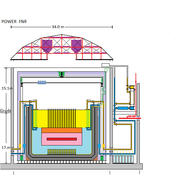
For simplicity, in the above diagram the air locks and the open steel lattice supporting the fuel bundles are not shown.
Only 1 of 48 heat transfer loops is fully detailed.
Color Code:
Red - Reactor Core, Steam Main
Pink - Reactor Blanket
Orange- Fuel Tube Plenum
Gold- Warmer NaK pipe
Yellow- hot sodium, hydraulic sodium tube, hydraulic lifter
Light Green - Intermediate Heat Exchange tubes
Dark Green - Hot wall thermal brake support, polar gantry bearings
Light Purple - Fiber Ceramic Insulation
Dark Purple - NaCl Reservoir
Light Blue- cool sodium
Dark Blue - Cooler NaK Pipe
Light Gray - Concrete
Dark Gray - Fire Brick
Black - Steel Outline
FAST NEUTRON REACTOR DESCRIPTION:
The FNR described herein has a primary sodium pool consisting of a cylindrical steel tank with outside dimensions 18 m high X 24 m diameter. The tank walls are three layers of steel separated from each other by two 0.96 m thick layers of granular NaF, so the tank inside dimensions are 16 m high X 20 m in diameter. Note that the thermal expansion of the inner steel cup is greater than the thermal expansion of the outer steel cups so the granular NaF must accommodate the differential thermal expansion.
The innermost steel cup contains the 15 m deep liquid sodium pool. The liquid sodium pool top surface is 1 m below the pool deck and is 1 m above grade.
Centrally positioned in the liquid sodium pool is a ~ 13.6 m diameter array of vertical closed end metal fuel tubes, each 6 m high X 9.525 mm outside diameter.
The outer two rings of the fuel tube array consist of 228 fuel bundle cooling positions.
The outer two rings are surrounded by a gadolinium skirt and a 3.0 m wide guard band of liquid sodium.
FUEL RODS:
The lower 4.2 m of the fuel tubes contain fuel rods.
The initial weight fractions of the core fuel rods are:
Pu = 20%
U = 70%
Zr = 10%
The initial weight fractions of the blanket rods are:
U = 90%
Zr = 10%
The purpose of the zirconium in both the core and blanket rods is to prevent plutonium from forming a low melting point eutectic with iron in the fuel tube alloy.
Details with respect to metallic FNR fuel are available at: Metallic Fuels: The EBR-II legacy and recent advances
FUEL TUBES:
Each fuel tube contains a 4.2 m high stack of metallic core and blanket fuel rods and sufficient liquid sodium to provide good thermal contact between the metallic fuel rods and the steel fuel tube inner wall. In each active fuel tube the fuel rod stack consists of 1.8 m of blanket rod on the bottom, 0.6 m of core rod in the middle and 1.8 m of blanket rod on top. Above the fuel rod stack is a 1.7 m high empty space known as the fuel tube plenum, in which inert fission product gases accumulate and are stored.
Thus the ~ 0.40 m thick X 10.0 m diameter reactor core region (shown in red on the profile diagram) is surrounded by a 1.2 m thick blanket region (shown in orange on the profile diagram). The blanket regions are realized with blanket fuel rods. Outside the blanket region is a 0.6 m wide cooling region for used active bundles which also acts as additional blanket.
The gadolinium skirt and the 3.0 m wide sodium guard band absorb atomic particles and gamma radiation tha escape from the fuel assembly.
NaK PIPES:
Immersed in the liquid sodium around the upper perimeter of the liquid sodium pool are 48 intermediate heat exchange bundles that transfer heat from liquid sodium to secondary NaK.
Connected to the intermediate heat exchange bundles are 96 X 16.0 inch OD secondary NaK pipes that transport heat from the intermediate heat exchange bundles to the NaK-salt heat exchangers. These pipes have flange connections inside the sodium pool space to allow intermediate heat exchange bundle replacement.
EARTHQUAKE PROTECTION SYSTEM:
The FNR is designed to safely withstand earthquake induced horizontal acceleration of up to 1.25 g________. During an earthquake the fuel assembly, which is mounted on low friction bearings, and much of the liquid sodium stays in place due to their own inertia while the sodium pool walls and pipe structure move with respect to the fuel assembly. Such an earthquake may cause high amplitude sodium surface waves to slosh almost to the ceiling level of the sodium pool enclosure.
FUEL TUBE BUNDLES:
The metal fuel tubes are in an array of alternating fixed and movable fuel tube bundles. Within each fuel bundle the fuel tube square array center to centre distance of:
9 / 16 inch = 0.0142875 m
provides dependable natural circulation of liquid sodium, efficient heat transfer from the fuel tubes to the liquid sodium and a critical fissile fuel concentration in the core zone that can be realized using single step electrolytic fuel reprocessing.
The fixed fuel tube bundles each contain 384 fuel tubes and the movable fuel tube bundles each contain 248 fuel tubes. Each of 464 movable active fuel bundles can slide vertically to withdraw 1.1 m with respect to the adjacent fixed fuel tube bundles.
Attached to the lifting point of each movable fuel bundle is a buoyant vertical metal indicator tube. Each movable fuel bundle's indicator tube projects 0.2 m to 1.3 m above the liquid sodium surface. This vertical position is monitored using an overhead laser scanner. Each indicator tube is horizontally stabilized by its own buoyancy.
The indicator tubes convey to overhead monitoring instrumentation data relating to each movable fuel bundle's: insertion depth in the matrix of fixed fuel bundles, sodium discharge temperature and gamma ray production.
The reactor core zone thickness is precisely set by controlled insertion of each movable fuel bundle into the matrix of fixed fuel bundles using a dedicated actuator. The actuator is located within the supporting open steel lattice. The more the overlap of the movable fuel bundle core fuel rods with the adjacent fixed fuel bundle core fuel rods the larger the reactor core zone thickness.
The relative overlap of the movable and fixed fuel bundles is adjusted so that at full load the movable fuel bundles have an average sodium discharge temperature of about 460 degrees C. The average sodium discharge temperature from each movable fuel bundle is obtained using the overhead scanner.
During an emergency such as an enclosure failure, gravity propelled liquid sodium, acting as a hydraulic fluid, will cause the movable fuel bundles to withdraw from the fixed fuel bundle matrix causing a reactor cold shutdown.
If a movable fuel bundle insertion depth problem is detected the affected movable fuel bundle is withdrawn 1.1 m from the fixed fuel bundle matrix. Thus a single actuator jam or movable fuel bundle jam does not physically affect the other movable fuel bundles except via a changed neutron flux in the horizontal plane.
Hydraulic tubing is routed through the bottom of the open steel lattice and provides the controlled insertion of each movable fuel bundle.
The movable fuel bundle actuators are periodically automatically cycled to ensure that they and their corresponding movable fuel bundles move freely.
The movable fuel bundle positioning actuators rely on two common liquid sodium hydraulic pressure pumps that will run occasionally due to small leaks past the hydraulic actuator valves. These pumps are submerged in the primary sodium to maintain suction head but their motors are above the primary sodium pool and are cooled with flowing argon.
PASSIVE FUEL BUNDLES:
The reactor contains four rings of passive fuel bundles that contain just blanket fuel which form the perimeter blanket.
COOLING FUEL BUNDLES:
The reactor contains two outer perimeter active fuel bundle storage rings. Irradiated used fuel bundles are stored in these two outer perimeter rings for six years to allow natural decay of fission products to occur before the used fuel bundles are removed from the primary liquid sodium pool.
When the cooling rings are occupied, the perimeter blanket around the core zone is effectively six fuel bundle rings or 1.8 m thick.
PRIMARY SODIUM HEAT TRANSPORT:
At full load the hot liquid sodium coolant flows by natural circulation from the top of the liquid sodium pool at 460 degrees C down between the intermediate heat exchange bundle tubes and then back to the bottom of the liquid sodium pool at about 400 degrees C. There is hot and cool sodium mixing at the bottom of the sodium pool.
The change in liquid sodium temperature while flowing past the intermediate heat exchange bundles is about 60 degrees C. The axial temperature gradient is about:
60 degrees C / 6 m = 10 degrees C / m which is modest. The extracted heat is normally used for electricity generation and/or district heating.
The maximum safe thermal output of this FNR is limited by the properties of its fuel tubes.
FNR PRIMARY SODIUM POOL PLAN VIEW:
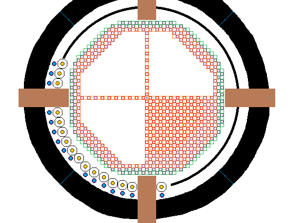
In the above diagram the outer black ring is the 2 m thick fire brick filled primary sodium pool wall. This wall consists of three nested steel cups with an inside diameter of 20 m and an outside diameter of 24 m. Inside the inner wall is an 17 m diameter ring which indicates the location of the intermediate heat exchange bundles. There are four gaps in this ring of heat exchange bundles, where brown indicates the positions of the air lock loading/unloading trays. Note that the cooler intermediate heat exchange bundle inlet pipes are thermally insulated and are oriented to face the corresponding heat exchange gallery.
Inside the ring of intermediate heat exchange bundles are the cooling, passive and active fuel bundles. Only one quadrant of fuel bundles is fully shown in detail. The movable fuel bundles forming the reactor core are shown in red. The passive movable fuel bundles that are jammed in the fully withdrawn position forming the reactor perimeter blanket are shown in purple. The fixed fuel bundles in both the core and the perimeter blanket are shown in orange. The fuel bundle cooling positions are shown in green.
The fuel tubes are packaged in bundles. Each active fuel tube contains both blanket fuel rods and a core fuel rod. There is a two dimensional matrix of fixed core fuel bundles in which the reactivity at any point in the matrix can be adjusted by adjusting the insertion depth of the appropriate movable fuel bundle into the matrix of fixed core fuel bundles.
The central core region together with the corresponding top and bottom blanket regions involve 945 vertical fixed and movable fuel bundles. There are 481 fixed active fuel bundles that form a 2 dimensional matrix into which 464 movable active fuel bundles are inserted from the bottom. Each fixed fuel bundle is 0.3286 m long X 0.3286 m wide X 8.0 m high and has 1.5 m high legs (corner girder extensions underneath the fixed fuel bundles). Each movable fuel bundle is 0.27146 m long X 0.27146 m wide X 8 m tall and has attached to its top a 6.8 m tall buoyant indicator tube. The movable fuel bundles are supported by actuators contained in the 1.5 m high open steel lattice.
RADIATION SAFETY:
The FNR fuel tube assembly perimeter is surrounded by a gadolinium curtain and a 3 m thick guard band of high purity liquid sodium. This sodium guard band absorbs all neutrons that escape from the assembly of fuel tubes. These absorbed neutrons convert natural sodium (Na-23) into Na-24 and a small amount of Na-25. The Na-24 naturally decays by electron emission with a half life of 15 hours to become stable Mg-24. In the decay process a 1.389 MeV gamma photon is emitted. After a reactor shutdown it takes about a week for this gamma radiation to drop by a factor of about 2000. If any of the fuel tubes are leaking or if the sodium purity or filtering is inadequate there could be other radio isotope emissions. For certainty with respect to gamma radiation safety, reactor physical security, certain sodium containment and certain water exclusion a FNR is surrounded by a ~ 1 m thick concrete wall resting on an ~ 2 m thick concrete foundation which in turn rests on bedrock.
Due to the gadolinium curtain and sodium guard band no neutrons reach the sodium pool containment walls or floor, the intermediate heat exchange bundles, the NaK, or the overhead structures. This prevention of neutron activation and neutron damage outside the fuel bundle assembly enables a very long facility working life and prevents formation of radioactive decommissioning waste.
During prolonged FNR operation a tiny amount of Na-25 will form in the sodium pool but it decays with a half life of about 60 seconds.
SURROUNDING EQUIPMENT INSIDE SODIUM POOL SPACE:
The sodium pool contains 48 immersed intermediate heat exchange bundles.
There is an overhead polar gantry crane in the reactor space that is used to install, reposition and remove sodium pool structural elements, fuel tube bundles, intermediate heat exchange bundles and related piping.
There are a total of four airlocks, each of which permits entry to and exit from the primary sodium pool space without loss of argon and without mixing of air and argon. Two air locks are intended for installation and removal of fuel bundles. The other two airlocks are larger to permit passage of service personnel, intermediate heat exchange bundles and gantry crane accessories.
To enable personnel entry and exit without pressure suits chemicals are used to absorb oxygen in the airlock that would otherwise mix with the argon cover gas.
The argon cover gas above the sodium is kept at atmospheric pressure. Its normal operating temperature is about 460 degrees C. When the reactor is cool shut down for service this temperature decreases to about 120 degrees C. Each FNR has large argon bladder tanks in its bassement to accommodate thermal expansion-contraction of the argon cover gas. Argon flowing from the reactor space to a bladder passes through a gas cooler which protects the bladder tanks from exposure to high temperature argon.
To the extent possible all work in the reactor enclosure is done using robotic equipment. Any entry by service persons requires both a prolonged (one week long) reactor shutdown to allow Na-24 decay and requires a thermally insulated and cooled suit fitted with a closed circuit breathing apparatus. Such entry may be necessary to repair a gantry crane defect or to replace a defective intermediate heat exchange bundle.
A potential issue related to manual service in the reactor space is possible accumulation of Kr-85 from leaking fuel tubes.
In the event of a fuel tube leak or fuel melting the contained nuclear fuel is denser than liquid sodium, so any leaked material will tend to sink to the bottom of the sodium pool where, provided that it is prevented from forming a critical mass, it poses no risk and can eventually be recovered from the bottom tray. Most potentially corrosive fission products are chemically trapped by the primary liquid sodium and can be recovered by filtering.
SURROUNDING EQUIPMENT OUTSIDE THE SODIUM POOL SPACE:
Outside the pool side walls and bottom is a 2.5 m wide mechanically cooled space stabilized with structural steel which in turn is enclosed by a ~ 1 m thick square concrete wall. The concrete extends 19 m below grade and 19.5 m above grade. The surrounding earth fill is of sufficient density and dryness to safely contain the liquid sodium even in the event of combined sodium pool and concrete wall structural failures. The earth fill also protects the FNR from the ground impact and fire that might result from the crash of a large airplane.
Outside the reactor enclosure in the 8 adjacent heat exchange galleries are 48 steam generators and 48 induction pumps. Below that level there are 48 NaK dump tanks. The heat exchange galleries have 1 m thick reinforced concrete outside walls and 1 m thick reinforced concrete end shear walls that provide additional structural protection against a low angle aircraft impact.
The spare space underneath the heat exchange galleries contains the argon bladders.
For safety purposes the NaK is kept at an absolute pressure less than the surrounding fluid pressure. The heat transport system remains safe in the presence of an intermediate heat exchange tube failure or a steam generator tube failure. Each NaK loop is vented to the atmosphere via ball checks and rupture disks. There is provision for absorbing NaK pressure hammer.
The concrete walls outside the heat exchange galleries are stabilized on the outside by the surrounding 19 m depth of dry ground. The elevation of the primary sodium pool with respect to the elevation of the local water table must be sufficient to prevent flood water reaching the sodium in any circumstance.
NaK HEAT TRANSPORT:
There is a 16.0 inch OD NaK pipe from each intermediate heat exchange bundle upper manifold to the corresponding steam generator upper manifold NaK inlet. There is a 16.0 inch OD NaK pipe from the steam generator lower manifold NaK discharge to the intermediate heat exchange bundle lower manifold via a flow meter and a vertical induction type circulation pump. The aforementioned pipes have accessible bolted disconnection flanges located close to the intermediate heat exchange bundles.
The NaK absolute pressure is normally less than the surrounding fluid absolute pressure to minimize NaK leakage at the flanged connections. The flange bolts are chosen to have a smaller TCE than the flange material to ensure that the flanged connections remain tight over their operating temperature range.
Normal NaK circulation is by induction pumping.
Normally the hot 10 MPa steam discharged from the steam generators flows under the adjacent laneway to the turbo-generator halls which are on the opposite side of the laneway.
The heat exchange gallery space is fitted with NaK vent pipes which in the event of a steam generator tube failure will vent the resulting steam and hydrogen to the atmosphere. In the event of a NaK fire the NaK flows by gravity into an argon covered dump tank to extinguish the fire. Further fire protection is provided by the external extinguishing agent Na2CO3.
There is sufficient natural circulation of NaK for fission product decay heat rejection when the NaK induction pumps are not energized. However, there must be a provisions for emergency gravity water feed into the steam generators.
The NaK loop components must be sized so that the natural circulation rate of the NaK will be sufficient to safely remove fission product decay heat after the nuclear chain reaction is shut down, even if the top 4 m of liquid sodium is missing from the sodium pool.
Each NaK dump tank has sufficient volume to accommodate all the NaK in its heat transport loop. NaK is transferred from the dump tank to the NaK heat transport loop by applying argon pressure over this dump tank while sucking argon from the corresponding NaK loop high point. The NaK loop needs a steam heater for Na melting. Note that the NaK loop
should be rated for a transient 1.7 MPa working pressure. Each NaK loop must be fitted with a high pressure relief valve and rupture disk safely vented to the atmosphere.
In the heat exchange galleries all equipment and pipes containing NaK should be further surrounded by a thermally insulating containment jacket for minimizing loss of heat, for fire prevention/mitigation and for personnel safety.
STEAM FLOW:
The steam pressure in each steam generator is normally controlled by a motorized steam pressure regulating valve which attempts to maintain a constant steam pressure (10 MPa). That pressure, via the pressure-temperature relationship for saturated steam, sets the water temperature at the base of the steam generator at about 310 C. In turn that sets the NaK low temperature at about 330 dgrees C.
The steam discharged from the steam generators flows to an adjacent turbogenerator and steam condenser. Controlling the NaK flow rate in effect controls the mass flow of constant pressure steam delivered to the corresponding turbo-generator. There are 8 steam turbogenerators and condensers. The condensers sink heat to a district heating system and to four independent natural draft cooling towers. The cooling towers are each sized for safe rejection of the reactor's maximum fission product decay heat (80 MWt).
The 8 steam to electricity conversion systems are completely isolated from one another except that each group of two shares a common on-site cooling tower. Each intermediate heat exchange bundle feeds a dedicated steam generator and has a dedicated NaK dump tank. Hence in the event of an equipment problem only a small fraction of the reactor output capacity need be shut down for service while the balance of the reactor capacity remains fully operational.
REACTOR MONITORING ELECTRONICS:
A FNR is controlled by several micro-computers. The main function of these micro-computers is to safely maintain the desired heat extraction rate and to trigger equipment or reactor shutdowns if any significant out-of-normal condition is detected. The monitoring software must include hardware watchdogs that can detect any significant problems within the reactor monitoring system or the movable fuel bundle actuator control systems. If any such problems are detected there should be an immediate reactor cool shutdown.
POOL FLOOR TRAY:
A FNR designed for electric power production has 945 active fuel bundles. Sooner or later through accident, negligence or malevolent behavior there will be a defective active fuel bundle and/or a defective movable fuel bundle actuator. In these circumstances the major concern is potential fuel melting. In response to local overheating the adjacent movable fuel bundles must immediately withdraw to ensure chain reaction shutdown in the defective movable fuel bundle.
If fuel tube melting occurs fuel alloy droplets might collect on the floor tray of the open steel lattice under the assembly of fuel bundles. It is essential that these droplets do not accumulate together to form a critical mass. The floor trays of the open steel lattice must hold a neutron absorbing material that is geometrically shaped to prevent fuel droplets from forming a critical mass. There should also be a practical means of selectively removing and replacing the floor trays.
This web page last updated May 25, 2025.